| ENGINE REASSEMBLY | 60 |
41. Push the kick starter down to turn the pressure plate. Check the pressure plate to see if it turns evenly. If it wobbles, the springs are not adjusted evenly.
42. Mark the point where the pressure plate is farthest from the rest of the clutch plates. Release the clutch and turn the nuts closest to the mark inward 1/2 turn. Repeat the test until the pressure plate runs true.
43. When reassembling a used clutch, the nuts must be turned in farther than with new plates. Use caution because if the nuts are turned in too far, the clutch will drag when disengaged and be hard to operate. The nuts will also be turned in too far for the cotter pins to hold them, and the rotation of the clutch will loosen them.
44. After proper adjustment, install a cotter pin through each nut and bend over. Safety wire is also acceptable, with the end twisted flat so i won't hit the inside of the primary case when the clutch is turning.
45. Remove the magneto side cover. Be sure not to lose the actuating plunger.
46. Install the flat retaining washer on the selector shaft until it touches the snap ring. Install the spring washer on top of it.
47. Be sure the engine case guide pins are in good condition.
48. Grease both sides of the new primary case gasket and install it.
49. Check the condition of the o-rings in the primary case. If in doubt, replace them.
50. Turn the engine so the primary drive faces upward. Pour a quart of SAE 30 motor oil into the engine. Be sure to thoroughly cover the primary drive components so they have lubrication when the engine is started.
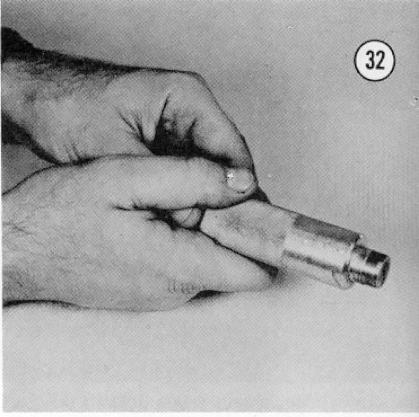
51. Install tool number 121-951 in the primary case selector shaft hole and tool number 121-951 in the kick starter shaft hole. Hold the tool and push the center sliding bar all the way inward (see Figure 32) and install it in the hole, where it will protect the o-ring from the splined shaft ends.
52. Install the primary case on the engine (see Figure 33) and tap) it with a soft mallet to seat it.
53. Install the ten screws, which are three different sizes (see Figure
34) in the appropriate holes. Tighten in the sequence shown.