FIG. 123
Page 85
21. Replace the sparkplug, and using a 13/16" deep socket, torque it to 18 ft. lbs.
22. You may want to leave the magneto cover off until the engine is put back into the frame and the chain has been installed. However, if you wish to install it now, coat the clutch actuating plunger with grease to keep it from falling out. There is no gasket between the magneto case and the engine, but it is recommended that the case be sealed with a good brand of silicone rubber sealer. Even though the Motoplat ignition can fire a plug when the magneto is drowned in water, it is a good policy to seal the case to protect the crankshaft oil seal and to keep moisture from corroding the metal parts.
23. Install the four magneto case mounting screws. The shortest one goes in the top rear hole; the longest one in the bottom rear hole; and the other two, being both the same length, can go in either of front holes. Tighten them securely with a large screwdriver or an impact screwdriver.
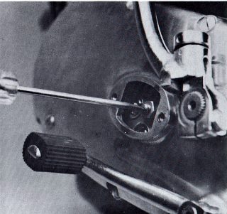
24. Move the clutch actuating arm back and forth. It should have at least 1/2" to 5/8" movement. If it does not, turn the engine around to the primary side and loosen and remove the two screws securing th6 small inspection cover in the middle of the case. Remove the cover and it exposes the clutch pressure plate with a pushrod adjusting screw and lock nut. Loosen the nut in the center of the pressure plate. Some models have a 13 mm nut and some use a 14 mm nut. With a screwdriver, turn the adjuster screw clockwise until it starts to bind (Fig. 123). At this point there should be no play at all in the clutch actuating arm. Then, turn the screw counterclockwise approximately two turns, or until there is 1/2" to 5/8" movement in the arm. Tighten the lock nut and recheck the movement of the arm. Reinstall the inspection cover, two lock washers and two screws. Tighten the screws securely.
25. The engine is now ready for installation into the frame.
FIG. 123
Page 85