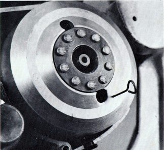
FIG. 118

FIG. 118
8. You will now need a dial indicator to locate the position of the piston while timing the engine. There are several types of dial indicators and sparkplug hole adapters available through most motorcycle accessory distributors or machinist supply firms. Since most of them are similar, the procedures for using them are usually the same.
9. Most timing dial gauge kits consist of a dial gauge calibrated either in millimeters or thousandths, an adapter that screws into the sparkplug hole, and a plunger that fits into the adapter, between the piston and the indicator (Fig. 119). To install the gauge, remove the sparkplug and screw the adapter tightly into the hole. Drop the plunger down through the center of the adapter and then set the dial indicator into the center of the adapter. With the timing pin still locking the magneto flywheel and stator together, push the dial indicator downward until the needle on the indicator begins to turn. When the needle has completed one full revolution, tighten the lock screw on the adapter which will lock the indicator in place.
10. Dial indicators all have a rotatable face so that you can move the numbers. Rotate the face so that the needle reads "zero." (Fig. 120).
11. Remove the timing pin and rock the magneto flywheel back and forth slightly. If the dial indicator needle does not move every time you move the flywheel, this means that the plunger is too short and will need to be lengthened or replaced with a longer one.
12. Once you are sure that the plunger is long enough, reinstall the
timing pin between the flywheel and stator. Check and reset the dial indicator
to zero if necessary. Then remove the timing pin and turn the flywheel
clockwise, counting the number of complete revolutions the large needle
makes before it stops moving. The point where the needle stops moving is
top dead center. Stop the flywheel at that point and add the number of
revolutions the needle made to the decimal fraction that the dial indicator
is reading. For example, if the large needle passed zero three times and
stopped at a reading of 15, then the ignition timing is 3.15 mm before
top dead center (B.T.D.C.).
Page 82