FIG. 110

FIG. 111
FIG. 110
FIG. 111
NOTE: Do not attempt to position the wrist pin by hammering it with a mallet, as this may bend the connecting rod. If the wrist pin proves difficult to move, use a wrist pin driving tool as shown in Fig. 111 to install the pin.
12. Using a pair of needle nose or duck bill pliers, install both wrist pin clips in the piston (Fig. 112). If you can rotate either of these clips in their grooves after installation, remove and discard them and install new ones.
13. Install both rings on the piston, making sure that the small peg in each ring groove is centered between the ends of the ring. Be certain that neither ring can bind in its groove. Squirt a few drops of oil on the rings and work it around to lubricate all of each ring.
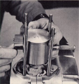
14. Remove the shop rag and turn the engine very carefully until the piston is at bottom dead center (B.D.C.). Slide the cylinder down over the studs until the bottom of the liner rests squarely on the top ring.
15. The bottom inside of the cylinder liner has a small chamfer machined around its circumference to make the rings easier to start into the cylinder. Using your fingers, or a ring compressor, compress the rings, being careful not to allow either ring to ride up over the peg in its groove or out of its groove. Carefully work the cylinder down over the piston and seat the cylinder against the engine cases (Fig. 113).
NOTE: A ring compressor can be easily fabricated from a hose clamp. Locate a clamp of sufficient diameter to encircle the piston. At three or four points around the circumference,
Page 78