FIG. 49
Page 34
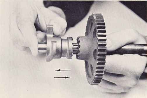
14. Check the splines on the end of the kickstarter shaft carefully for damage and wear. Inspect the teeth on the kickstarter driving gear and spin the gear on the kickstarter shaft to be sure it turns freely. Also, inspect the ratchet teeth on the gear. Check the ratchet teeth on the ratchet cam and push the cam back and forth on the shaft (Fig. 49). You should be able to move the cam approximately .4" towards the right end of the shaft, and it should return by the pressure of the spring.
15. Remove the kickstarter stop bolt from the right engine case. It is threaded into the case and secured by a 14 mm lock nut which is accessible through the hole in the outside rear of the case (Fig. 50). Loosen and remove the lock nut, steel washer and fiber washer. Then, unscrew the stop bolt. Check it for cracks or other signs of fatigue. If you suspect it to be faulty, replace it with a new one. Clean the threads on the bolt, the lock nut, and the threads in the engine case thoroughly. Put several drops of Loctite on the threads of the nut and bolt, and screw the bolt back into the case. Turn it with your fingers until it will go no further. The bottom of the head of the bolt should be about .080", or 2mm from the shoulder of the case. Install the fiber washer, steel washer, and lock nut, and tighten to 20 ft-lbs of torque.
16. Check the selector return spring anchor pin for wear or looseness in the case. If you remove it for any reason or replace it, always
FIG. 49
Page 34