FIG. 29
FIG. 29
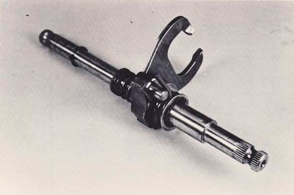
7. The shifting drum is actually turned by the movement of the selector shaft assembly (Fig. 29). This is the shaft onto which the gearshift lever is bolted. Because this shaft passes all the way through the engine, a shift lever may be bolted to either end.
8. The selector shaft assembly is comprised of the selector shaft itself, a spring loaded selector pawl, a selector return spring and a gearshift lever. When the selector shaft is rotated by moving the gearshift lever, the selector pawl engages one of the selector pins on the shift drum, and turns the drum to the next gear postion. When the shift lever is released, the selector spring pulls the selector shaft back to its original position. As this happens, the selector pawl, being spring loaded, snaps over top of the next selector pin and is ready for the next gear change. The selector shaft assembly is designed so that the shift drum can only be turned enough to engage the next closest gear every time the lever is moved. In other words, if the transmission is in 3rd gear, one upward movement of the gearshift can only allow 4th gear to be engaged. One downward movement can only allow engagement of 2nd gear.
9. The OSSA engine uses a foot operated, kick-type starting system. This system operates through the mainshaft of the transmission and the kick starter assembly (Fig. 30). This assembly consists of the kick starter shaft, a spring loaded kick starter ratchet cam, a kick starter driving gear, a kick starter return spring, a kick starter lever and a kickstarter stop bolt, which is threaded into the right engine case.
Page 18