11. Ignition Switch. There is no voltage regulator in this system.
The battery acts as a voltage stabilizer. Because the battery is wired
to the circuit in parallel, it need not be in the system in order for the
lights to work. However, when the battery is removed, the lights work directly
off the generator. Because the generator voltage is proportional to the
engine R.P.M. it is possible for the light bulbs to blow out at high engine
speed. The battery ground wire is connected to a black wire that runs up
to the ignition switch. When the ignition switch is turned on, the battery
is grounded. When the ignition switch is turned off, the battery is not
grounded. If the ignition switch is turned on, and for any reason the switch
is faulty and the battery is not grounded, the battery will not receive
a charge. Also, because the battery is not in the circuit when it is not
grounded, light bulbs may blow out due to the excessive current generated.
To check the ignition switch, disconnect the ground wire of the battery
from the black wire it is plugged into and remove the fuse from its holder.
Clip one lead of the ohmmeter to the black wire and clip the other lead
to ground. With the ignition switch in the "off" position the meter should
read infinity. When you turn the ignition switch on, the meter should read
zero. (Fig. 153) If the switch fails this test, check the wires on the
back of the switch to be sure that it is wired correctly. If the wires
are correctly installed, replace the ignition switch. Plug the ground wire
of the battery back into the black wire and reinstall the fuse.
12. There always exists the remote possibility that one of the electrical
components (horn, taillight, etc.) has an internal short and is putting
an excessive load on the electrical system.
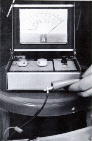
FIG. 153
13. To check this, disconnect the positive wire of the battery at the connector
located between the fuse and the battery. The battery must have at least
six volts to conduct this test. You will also need a DC ammeter. Clip the
red, or positive lead of the ammeter to the end of the wire that has the
fuse on it. Clip the negative lead of the ammeter to the end of the wire
that goes to the battery. (Fig. 154) Turn the ignition switch on, but do
not start the engine. Leave the light switch in the "off" position. Because
there are no electrical components in use the ammeter should read zero.
If it does not, there is a short somewhere in the electrical system.
Page 122