FIG. 150
FIG. 150
8. If the readings were not within these tolerances, the individual components of the lighting system will need to be checked.
9. Resistor. Remove both wires from the terminals of the resistor. Place one lead of an ohmmeter on one of the terminals; the other lead on the other terminal. The meter should read 14.5 to 15.5 ohms. If it does not, replace the resistor. Remove one of the ohmmeter leads from either resistor terminal and place it on either of the mounting nuts, leaving the other end on the other terminal. If you get any reading whatsoever besides infinity, replace the resistor.
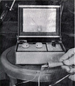
10. Headlight control switch. With the two connectors still removed from the resistor, clip one of the ohmmeter leads to one of these connectors and clip the other lead to the other connector. Remove the fuse from the fuse holder. Turn the headlight on-off switch to "off." The meter should give no reading at all, or infinity. (Fig. 150) Turn the headlight switch on and the meter needle should move to zero. If the switch does not pass these checks, disassemble and examine it closely for dirt, corrosion, or damage. When the switch is in the "on" position, the metal bar that connects terminal No. 3 and terminal No. 8 bridges the two terminals. When the switch is turned off, the switch arm pushes the bar upward, breaking contact. Figs. 151 and 152 illustrate this. Replace the switch if it cannot be made to function properly. Put the fuse back into the fuse holder.
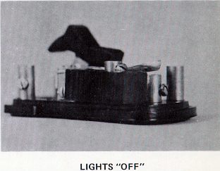
FIG. 151
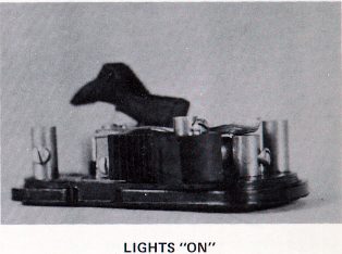
FIG. 152
Page 121